Linkage kits are available for the mechanical connection from the actuator crank arm to the load lever arm. Beck’s linkage kits help move your control by eliminating slop in your linkage connection.
When a linkage connection is properly sized, designed, and implemented it will help ensure that you have a successful, long-lasting installation. Beck Engineers are available to assist you with designing your linkage and specifying the appropriate linkage kit through our free Link-Assist service. Beck offers two different styles of linkage kits and hex linkage kits.
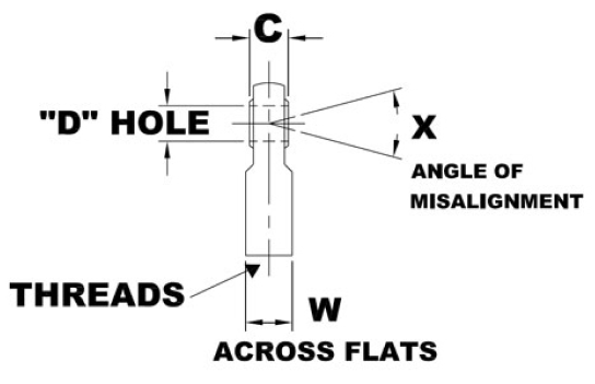
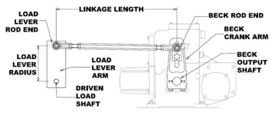
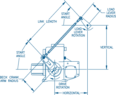
BASIC LINKAGE TERMINOLOGY

Beck provides a complementary service called Link-Assist to support the setup and installation of our linkage connected actuator products. Link-Assist is an exclusive linkage program that provides Beck Engineers the ability to design an optimal linkage configuration based on your application specific constraints. Beck can supply you with the recommended linkage length, crank/lever arm start angles, and crank/lever arm radii. This information is available in a date-stamped comprehensive report that also provides the delivered torque and force profiles throughout travel.
Link-Assist reports can be generated for new installations or to ensure optimal setup of existing installations. Download a sample of a completed Link-Assist Report by clicking the to the right.
What Information Is Required To
Obtain A Link-assist Report?
Watch the following video for instructions on how to obtain the necessary information for Beck to provide you with a Link-Assist report.
Selection charts, diagrams, and downloadable drawings on both linkage kit styles are available frorm the right-hand sidebar menu on this page.
PIPE LINKAGE KITS
Pipe linkage kits provide the maximum flexibility for linkage length requirements between 22″ and 120″
HEX LINKAGE KITS
When well-defined, short lengths are required, Hex Linkage Kits can be used. The hex linkage kits range from 9″ to 33″ depending on the application requirements
Linkage setup worksheets are available for download to make it easier for recording the data shown in the video to the left.
Several worksheet orientations are provided, so that you may select the most appropriate for your application.
Once completed, the worksheets may be faxed to Beck at 215-860-6383 or emailed to sales@haroldbeck.com.
A Sales or Application Engineer will evaluate and process your Link Assist promptly.
Please be sure to include your telephone number, fax number or email address.
Download Linkage Worksheets