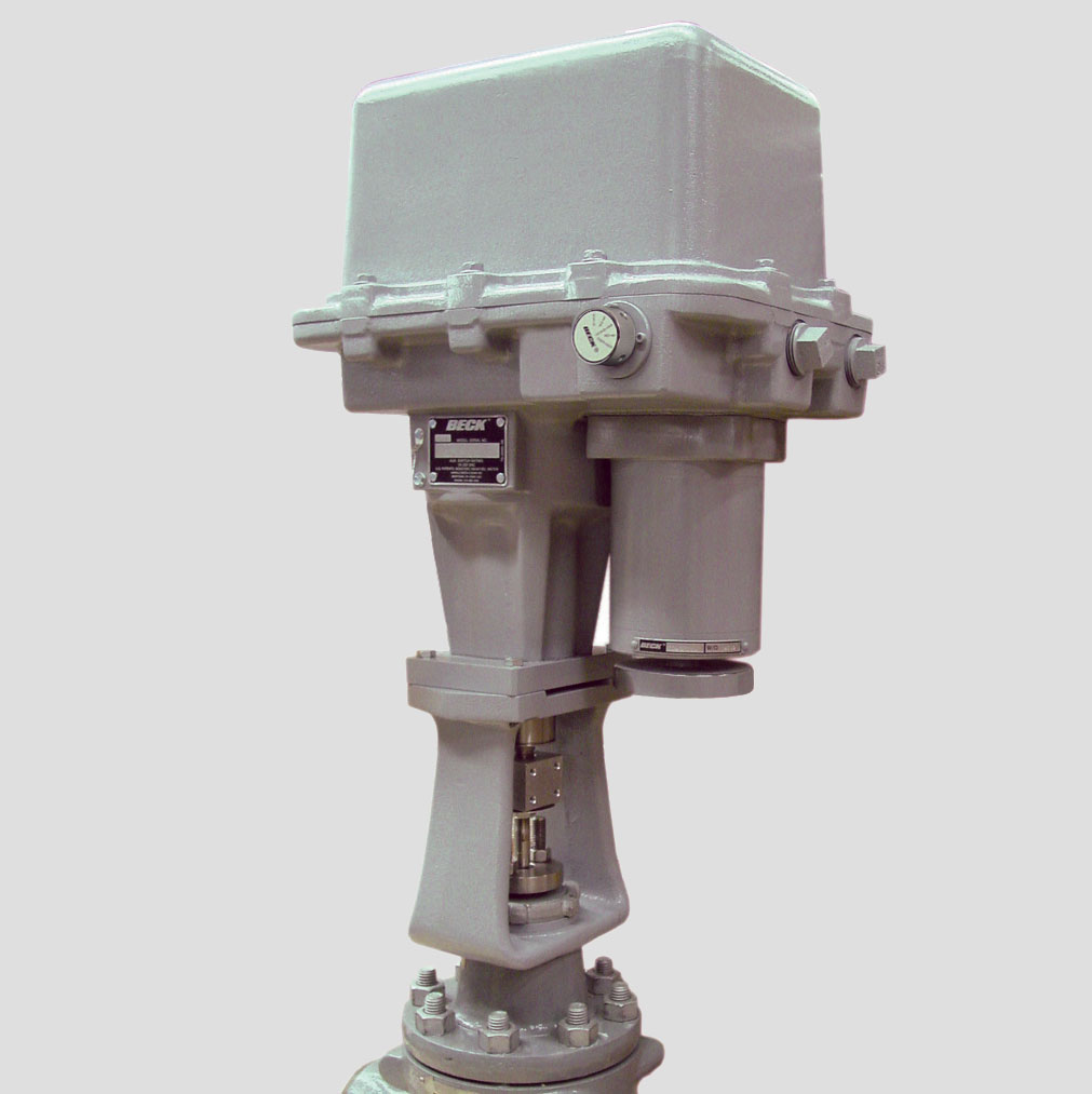
HEAVY DUTY LINEAR ACTUATORS
Group 29 Beck drives offer the benefit of a total control package, utilizing reliable electronics to match the speed and precision of your process instrumentation.
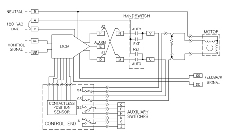
Standard Group 29 modulating drives (control option 9) are equipped with Beck’s Digital Control Module (DCM), which controls the position of the drive according to the input signal it receives. A position feedback signal is delivered to the DCM from the position sensing device (Beck’s Contactless Position Sensor (CPS-4)).
This signal is continuously compared to the demand input signal. A change in the input signal results in an immediate repositioning of the drive to balance the two signals.
AVAILABLE THRUST AND TIMING COMBINATIONS FOR THE MODEL 29-100
(LBF)
(INCHES)
(SECONDS/INCH)
Beck’s DCM provides modulating control of the drive in response to standard control system signals.
Notable features include:
- Convenient user interface for calibration and drive status.
- HART® compatibility.
- Compatible with common asset management systems.
- Receives control signals directly, eliminating the need for contact protection devices, relays, switches and reversing starters.
- Designed to operate continuously at temperatures from -40º F to 185º F (-40° to 85° C).
- Initiates shaft movement in steps ranging from 0.10% to 0.25% of span, depending on the timing of the gear train.
Beck’s patented CPS-4 technology has been providing reliable control feedback with infinite resolution in our products for many years.
- Utilizes a unique ferrite magnetic design with no contacting or wiping surfaces to wear or intermittently lose contact.
- The ferrite rotor is driven directly by the output shaft through anti-backlash gearing.
- A 4–20 mA position feedback signal is available for remote indication.
FACTORY CALIBRATION
All Beck drives are set-up and calibrated to the customer specification. No electrical adjustments are required before installation. Additional features available on Beck control electronics:
Like all Beck drives, the Group 29 utilizes a low current draw, continuous duty motor design. This motor ensures that the drive will not coast or overshoot and will not overheat, even under continuous modulation. The net result is consistent, repeatable positioning with no duty limitations.
Similar to all Beck drives, the Group 29 is equipped with an override manual Handswitch to aid in the setup and installation of the drive independent of external control signals.
Up to two optional non-dedicated Form C switches are available. These switches are cam-operated and easily adjusted in the field. Wiring connections are provided in the drive terminal compartment to allow easy access.
FACTORY CALIBRATION
All Beck drives are set-up and calibrated to the customer specification. No electrical adjustments are required before installation. Additional Features available on Beck Control Electronics
The Group 29 linear globe valve actuator utilizes a high-efficiency gear train designed for performance, long life, and minimal wear. It consists of a combination of precision-cut alloy steel and ductile iron spur gears and a precision ball screw. Beck Spur gears are exclusively made at our factory to ensure the high quality demanded of the Group 29 products.
Manual Operation
Group 29 linear valve drives can be manually operated, without power, by a Handwheel directly connected to the drive motor shaft. This allows positioning of the valve in the absence of AC power.
Tight-Seater™
Group 29 linear valve drives are equipped with a Tight-Seater™ device that ensures the valve is positively seated at the closed position.
Self-Locking Mechanism (SLM)
A self-locking mechanism is an integral part of the Group 29 linear valve drive system. The SLM is a coupling that transmits motor torque to the gear train, but instantly locks in place when the motor is de-energized. This prevents back-driveing due to dynamic valve load.
FACTORY CALIBRATION
All Beck drives are set-up and calibrated to the customer specification. No electrical adjustments are required before installation. Additional Features available on Beck Control Electronics
CONTROL OPTION
Group 29 Beck linear actuators have a model number 29-100, 29-250, or 29-600. This drive has the capability to be equipped with different electronics combinations, which are called control options. The control option number will replace the last zero in the model number when specifying a drive model and control option. For example, a model 29-100 drive that is setup to use the control option 9 electronics would be considered a model 29-109 drive. A basic description for each control option is provided below. For details on the electronics components, please visit the Group 29 Electronics section.OPTION
DESCRIPTION
The standard modulating drive offering is the control option 9. Control option 9 units are equipped with the Beck DCM (Digital Control Module) and CPS(Contactless Position Sensor). The option 9 drives may be controlled with a 4-20 mA or 1-5Vdc signal and have an integral 4-20 mA position feedback signal. The microprocessor based DCM provides a multitude of flexibility for setup, calibration, and diagnostics including HART communications, on-board pushbuttons for calibrating stroke, on-board diagnostic status, stall protection circuitry, and status alerts.
OPTION
Output Thrust and Timing
Model Number | Thrust (lbs.) | Stroke Timing (seconts/inch) | Maximum Stroke Length |
29-100 | 1,000 | 10 | 2″ |
29-250 | 1,700 | 10 | 2″ |
29-250 | 2,100 | 12.4 | 2″ |
29-250 | 2,700 | 15 | 2″ |
29-600 | 2,100 | 9.4 | 4″ |
29-600 | 2,600 | 11.6 | 4″ |
29-600 | 3,200 | 14 | 4″ |
29-600 | 4,100 | 9.4 | 4″ |
29-600 | 5,000 | 11.6 | 4″ |
29-600 | 6,100 | 14 | 4″ |
Drive Power Options
(all Group 29 models)
120 Vac, single-phase, 50 or 60 Hz |
240 Vac, single-phase, 50 or 60 Hz |
Additional Specifications
Weight (including yoke) |
Showing 1 to 2 of 2 entries
|
|||
Operating Conditions | –40° to 85° C. (–40° to 185° F.) 0 to 99% relative humidity | |||
Communications Interface | HART© protocol and local pushbutton/LED panel and RS-232 serial commands | |||
Demand Input Signal Range |
4–20 mA, 1–5 V dc | |||
Minimum Step | 0.1° of span | |||
Hysteresis | 0.25% of span at any point | |||
Demand Input Signal Characterization |
Linear: Drive output shaft moves proportionally to the input signal. Square: Drive output shaft moves proportionally to the square of the input signal. Custom: 20 segment configurable curve fit |
|||
Position Feedback Signal | 4–20 mA, 1–5 V dc | |||
Isolation | Demand input and position Feedback signals are isolated from ground and the ac power line. Signal buffering provides 24 V dc isolation between the Demand and Feedback signals. | |||
Action on Loss of Power | Output shaft stays in last position | |||
Action on Loss of Input Signal (Power on) | Stay in place or runs to any preset position (configurable) | |||
Over-thrust Protection | If the output thrust of the drive exceeds 115% of the drive rating, the motor will shut off (feature can be enabled / disabled). | |||
Stall Protection | If the motor tries to run in one direction for more than 300 seconds (configurable from 30 to 300 seconds), the motor will shut off. | |||
Over-travel Protection Switches | Two Form C (Retract and Extend) provide over-travel protection | |||
Auxiliary Switches (Field Adjustable) |
Two Form C and two Form A, all rated for 1 A, 250 V ac | |||
Customer Wiring | Terminals accommodate up to 12 AWG (3.31 mm^2) | |||
Handswitch | Permits local electrical operation, independent of Demand input signal. | |||
Handwheel | Provides manual operation without electrical power. | |||
Motor | 120 Vac, single-phase, no burnout, noncoasting. Capable of 60 starts per minute | |||
Enclosure | Precision-machined aluminum alloy castings, painted with corrosion-resistant polyurethane paint, to provide a rugged, dust-tight, weatherproof enclosure designed to meet NEMA 4X standards. | |||
Mounting Orientation | Can be mounted in any orientation |
HOW TO ORDER
Beck Group 29 drives are furnished with custom hardware for valve connection. The following instructions are intended to make it easy to specify and order Beck Group 29 linear valve actuators. If questions arise concerning additional options or control modes, contact your Beck Sales Engineer.
Complete instruction manuals are furnished with each drive order.
- Modulating Operation – Model 29-109, 29-259, or 29-609
- Open/Close Operation – Model 29-103, 29-253, or 29-603
- Desired Thrust and Timing Configuration
- Desired control input signal
- Desired power (120 or 240 V, 60 or 50 Hz)
- Direction of operation desired on increasing signal: Retract (RET) or Extend (EXT)
a. Valve specification including:
- Beck-supplied or Customer-supplied
- Manufacturer
- Size
- Style
- Materials of construction
b. Characteristics of flowing media.
c. Maximum, normal and minimum inlet pressure.
d. Maximum, normal, minimum and shutoff pressure drop.
e. Maximum, normal and minimum flow rate and direction.
f. Line size and schedule including flange requirements.