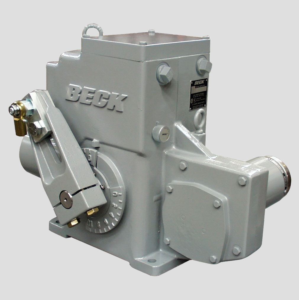
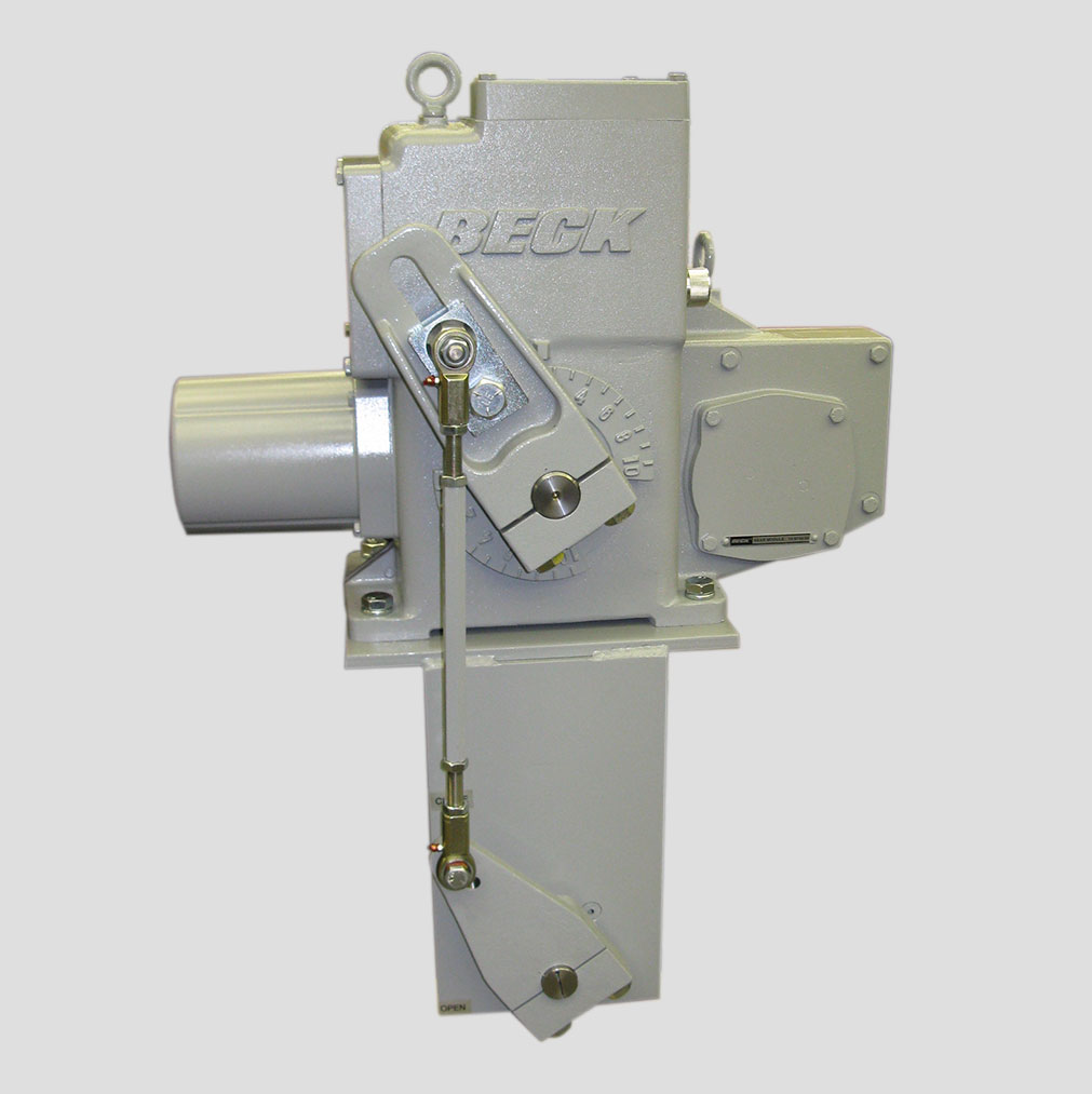
Model 11-200
Group 11 rotary damper drives and actuators offer the benefit of a total control package, utilizing reliable electronics to match the speed and precision of your process instrumentation.
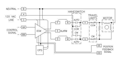
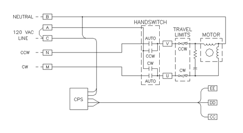
Standard Group 11 modulating drives (control option 9) are equipped with Beck’s Digital Control Module (DCM), which controls the position of the drive according to the input signal it receives. A position feedback signal is delivered to the DCM from the position sensing device (Beck’s Contactless Position Sensor (CPS)).
This signal is continuously compared to the demand input signal. A change in the input signal results in an immediate repositioning of the drive to balance the two signals.
AVAILABLE TORQUE AND TIMING COMBINATIONS FOR THE MODEL 11-200
(LB-FT)
(SECONDS/100°)
Beck’s DCM-3 provides modulating control of the drive in response to standard control system signals.
Notable features include:
- Convenient user interface for calibration and drive status.
- HART® compatibility.
- Compatible with common asset management systems.
- Receives control signals directly, eliminating the need for contact
protection devices, relays, switches and reversing starters. - Designed to operate continuously at temperatures from -40º F to 185º F (-40° to 85° C).
- Initiates shaft movement in steps ranging from 0.10% to 0.25% of span, depending on the timing of the gear train.
Beck’s patented CPS-5 technology has been providing reliable control feedback with infinite resolution in our products for many years.
- Utilizes a unique ferrite magnetic design with no contacting or wiping
surfaces to wear or intermittently lose contact. - The ferrite rotor is driven directly by the output shaft through
anti-backlash gearing. - A 4–20 mA position feedback signal is available for remote indication.
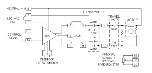
The analog Electronic Signal Receiver (ESR-5), which is standard in control option 7 and control option 8 drives, is an alternative to the intelligent, digital control module. The timeproven ESR provides the same excellent drive control but lacks many added setup, operating, and diagnostic features afforded by the DCM-3.
FACTORY CALIBRATION
All Beck drives are set-up and calibrated to the customer specification. No electrical adjustments are required before installation. Additional features available on Beck control electronics:
Together with Beck’s control electronics and rugged gear train, Beck motors provide the precise, reliable positioning required for modern control loops.
- Never overheats or burns out, even under demanding modulating control or stalled conditions.
- Reaches full speed and torque in less than 50 milliseconds and stops within 25 milliseconds, eliminating deadtime.
- Provides extremely accurate positioning in modulating applications.
- Will not coast or overshoot the desired position.
- Low current draw of 0.16 A to 3.0 A, and therefore low power consumption, eliminates the need for relays and permits the use of uninterruptible power supplies.
- Maintenance-free with double-lipped, grease-sealed bearings.
Dampers or valves may be operated at their individual locations with the built-in electric Handswitch. This saves time during installation and troubleshooting, allowing on-line adjustments to be made quickly and easily by bypassing the electronics in the drive and control system.
The Handswitch also serves as an electrical backup in the event of control system failure.
Two over-travel limit switches and up to four auxiliary switches are provided on Beck drives.
- SPDT switches rated for a minimum of 6 A at 120 V ac, (three times maximum motor current for most models) to ensure long life.
- Field-adjustable to operate at any point in the drive’s travel range.
- May initiate secondary functions or provide remote indication of drive position.
- Eliminates unreliable and maintenance- intensive proximity switches.
FACTORY CALIBRATION
All Beck drives are set-up and calibrated to the customer specification. No electrical adjustments are required before installation. Additional features available on Beck control electronics:
Beck’s durable gear train maintains accurate, consistent control element positioning even under the demanding conditions of an active control loop.
- Gear trains employ a unique, all spur gear construction of heat-treated alloy steels and ductile iron.
- Efficient, wide-face spur gearing virtually eliminates wear-induced backlash and positioning inaccuracies.
- Durable design provides up to 4 days of protection against intermittent or extended accidental stalls.
- Integral self-locking mechanism ensures that drives hold a load with the motor de-energized.
An easy-to-turn, spoke-free Handwheel is incorporated into the Group 11 design to allow manual operation during installation or power outages.
- Move valves and dampers to any position smoothly and easily without power, even under full load conditions.
- Mechanical stops in housing prevent manual overtravel.
Drive cutaway view displaying
individual compartments
Beck drives feature a cast aluminum body with individual compartments to protect components from moisture and dirt, and allow easy access for installation and calibration.
- Precision-machined aluminum alloy castings with corrosionresistant poly-urethane paint provide a rugged, dust-tight, weatherproof NEMA 4X enclosure.
- Individual compartments protect all major components: Motor, DCM, CPS-2, gear train and installation wiring terminal board.
- Each compartment can be accessed without exposing other components.
Group 11 Beck drives are designed to be mounted in any convenient position. The no oil bath design eliminates the potential for leaks.
As long as housing compartments remain accessible, there are no mounting orientation limits.
FACTORY CALIBRATION
All Beck drives are set-up and calibrated to the customer specification. No electrical adjustments are required before installation. Additional features available on Beck control electronics:
Control Options
Group 11 Beck drives have a model number such as 11-150, 11-160, 11-200, 11-260, 11-300, 11-360, 11-400, 11-460, or 11-430. Each of these drives has the capability to be equipped with different electronics combinations, which are called control options. The control option number will replace the last zero in the model number when specifying a drive model and control option. For example, a model 11-400 drive that is setup to use the control option 9 electronics would be considered a model 11-409 drive. A basic description for each control option is provided below. For details on the electronics components, please visit the Group 11 Electronics section.OPTION
DESCRIPTION
The standard modulating drive offering is the control option 9. Control option 9 units are equipped with the Beck DCM-2 (Digital Control Module) and CPS(Contactless Position Sensor). The option 9 drives may be controlled with a 4-20 mA or 1-5Vdc signal and have an integral 4-20 mA position feedback signal. The microprocessor based DCM provides a multitude of flexibility for setup, calibration, and diagnostics including HART communications, on-board pushbuttons for calibrating stroke, on-board diagnostic status, stall protection circuitry, and status alerts.
OPTION
DESCRIPTION
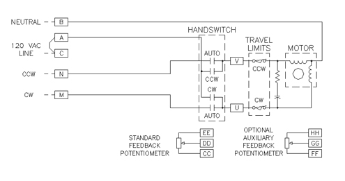
The control option 7 drive is a modulating unit that is offered without an external position feedback signal. The option 7 drive is equipped with the ESR (Electronic Signal Receiver) for control and a 1000- ohm film potentiometer to derive an internal position reading. While the standard control option 7 units may be controlled by a 4-20 mA signal, less common signaling options are availble upon request. An optional auxiliary pot for external position feedback is also available upon request.
OPTION
OPTION
OPTION
OPTION
Modulating Control
| Digital Control Module (DCM) | Electronic Signal Receiver (ESR) | Direct AC | |
|---|---|---|---|
| Input Signal Options | See Control Option 9 | See Control Option 7 | N/A |
| Adjustability for Split Range Operation | 4 to 1 | 2 to 1 | N/A |
| Deadband | 0.6% of span (configurable) | 0.6% of span | N/A |
| Minimum Step | 0.1% typical | 0.15% typical | 0.1° function of control system capabilities |
| Feedback Options | See Control Option 9 | See Control Option 7 | See Control Option 5 & 6 |
| Stall Protection (Protects drive and driven elements under stall conditions) | Standard. Integral to electronics. Time to stall is configurable from 300 seconds down to 30 seconds. | Optional. Requires a Stall Protection Module (SPM) to shut off power to the motor. | |
Note: (1) Models approved for use in Hazardous classified locations are available—contact a Beck Sales or Application Engineer for details.
Input Power
120 V ac, single-phase
240 V ac, single-phase
Operating Conditions
-40° to 85° C. (-40° to 185° F.), 0% to 99% relative humidity
Isolation
Demand Input and Position Feedback signals are isolated from the ground and the ac power line.
Action on Loss of Power
Stays in place.
Action on Loss of Input Signal
(Power On)
Stays in place or, on some drives, is field configurable to move to any preset position.
Limit Switches
Two SPDT switches (one for each direction of travel) provide over-travel protection.
Auxiliary Switches
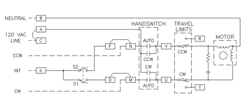
Up to four 6 A, 120 V ac switches available. Switches are labeled S1 to S4 and are cam-operated and field-adjustable.
Handswitch
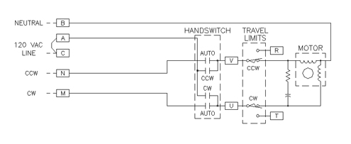
Permits local electrical operation, independent of controller signal. Standard on all units. An optional auxiliary contact can be used to indicate that the Handswitch is in “AUTO” mode or to sound an alarm if it is taken out of
“AUTO”.
HOW TO ORDER
Beck Group 11 drives are available in five basic models, and are furnished with a crank arm and rod end for linkage connection. When the drive is to be used in a multi-revolution mode, a sheave is furnished instead of a crank arm for use with wire rope. The following instructions are intended to make it easy to specify and order Beck Group 11 drives. If questions arise concerning additional options or control modes, contact your Beck Sales Engineer.
Complete instruction manuals are furnished with each drive order.
- Basic model number
- Control option
- Torque (lb-ft)
- Timing (sec./100°)
- Number of auxiliary switches
Using the information above, fill out the full model number according to the following formula:

- Desired control input signal
- Desired power (120 or 240 V, 60 or 50 Hz)
- Direction of rotation desired on increasing signal: Clockwise (CW) or
- Counterclockwise (CCW)
- Desired optional control features


